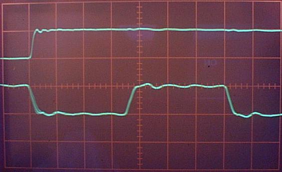
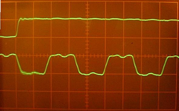
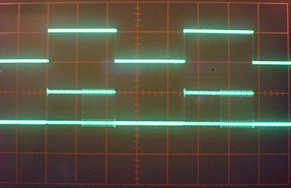
44.1 KHz source, word clock on top, bit clock on bottom, triggered on the positive-going word clock. Word clock period is 44.1 KHz. Bit clock is ~2.8 MHz.
44.1 KHz source, word clock on top, bit clock on bottom,
triggered on the positive-going word clock.
Word clock period is 44.1 KHz.
Bit clock is ~2.8 MHz.
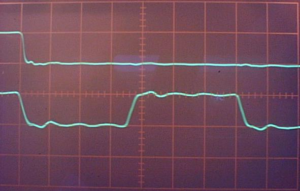
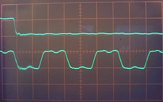
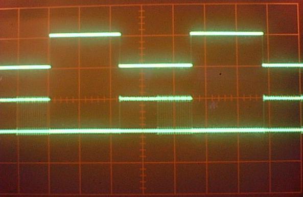
44.1 KHz source, word clock on top, bit clock on bottom,
triggered on the negative-going word clock.
Word clock period is 44.1 KHz.
Bit clock is ~2.8 MHz.
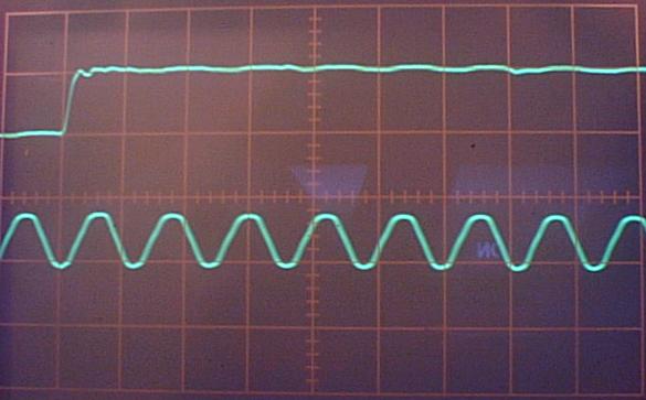
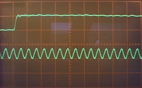
44.1 KHz source, word clock on top, Master clock (DAC clock) on bottom,
triggered on the positive-going word clock.
Word clock period is 44.1 KHz.
Master Clock is ~16.9 MHz.
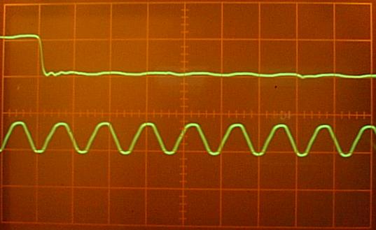
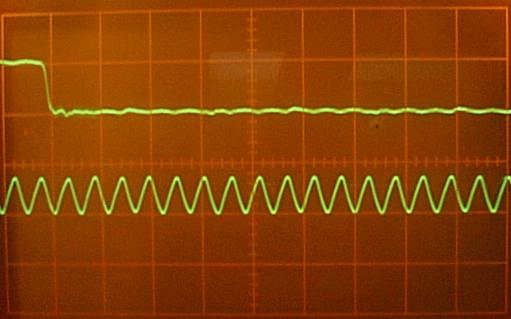
44.1 KHz source, word clock on top, Master clock on bottom,
triggered on the negative-going word clock.
Word clock period is 44.1 KHz.
Master Clock is ~16.9 MHz.
96 KHz source, word clock on top, bit clock on bottom,
triggered on the positive-going word clock.
Word clock period is 96 KHz.
Bit clock is ~6.1 MHz.
96 KHz source, word clock on top, bit clock on bottom,
triggered on the negative-going word clock.
Word clock period is 96 KHz.
Bit clock is ~6.1 MHz.
96 KHz source, word clock on top, Master clock on bottom,
triggered on the positive-going word clock.
Word clock period is 96 KHz.
Master clock is ~36.9 Mhz.
96 KHz source, word clock on top, Master clock on bottom,
triggered on the negative-going word clock.
Word clock period is 96 KHz.
Master clock is ~36.9 Mhz.
Note that all signals should be square waves, and the 150 MHz scope should have plenty of speed to see these KHz to 30 MHz signals. The rounding, especially of the master clock could be band limiting designed to cut down on RF noise. Or it could be a result of the circuitous path the clock travels before it finally reaches the DAC (or both :-). Some of the rounding could also be due to the ad-hoc clip lead I used on some of the shorter jumpers. With the probe connected directly they showed a little more bandwidth, but were still not square. I may also want to be more particular about the probe grounding.
If the master clock next to the clock generator is crisper looking it may be worth picking up there.
Next, the probes are connected to Word clock and ADAT2, which is the digital audio data after the AC-3 switch position. (The same trace is re-labelled DIN, presumably for 'Data IN', at the DAC chip.) Word clock is the top trace, Data is the bottom trace. The signal source is the Denon Audio Test Disc (44.1 CD) with 1001 Hz sine waves recorded at 0 dB. As above the vertical scale is 5V per major division. But here each major horizontal division is 5 uS, in order to show both audio channels.
The above is with a sine wave on the left channel only,
so the Pioneer clocks the left channel on the rising L/R Word clock.
Note also that the data is right justified (data bits appear towards
the end of the word pulse).
This is with data on the right channel only.
Right channel data is clocked on the falling Word clock.
Next: How these DV-414 waveforms compare to I2Se timing requirements